Firstly we need to know about basic things like Coil, Pole Pitch, commutator pitch, and Span for a better understanding of these words in the DC machine.
Table of Contents
What is the coil?
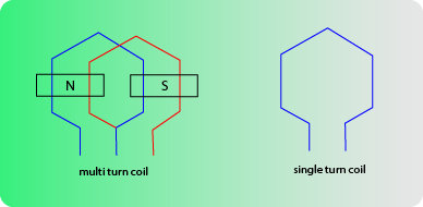
The coil of the DC machine uses copper (mainly enameled copper). Some of the machines have a single turn and some have Multi turns of the conductor to make a coil.
What is Single turn coil?
A single turn coil is a coil that has only one turn or loop of the conductor. It has less conductor usage to make a coil as compared to the multi-turn coil. The coil has multiple turns of the conductor, it is a multi-turn coil. It makes magnetic North and Magnetic South poles. Also, Single turn coil has one coil side in one slot.

What is a Multi-turn coil?
A Multi-turn coil has multiple turns or loops to make a single coil. Same as single turn coil it makes only one Magnetic North and South pole. The above picture of the multi-turn coil illustrates it well. Hence, this confirms that one slot will have multiple coil sides. As a result, all the conductors of one side of the coil are placed in one armature slot.
Coil Span and Pole pitch are the measurements of a DC or AC machine winding. Coil span and Pole pitch selection are as per the requirements of the different types of motor or generator accordingly. Pole pitch has short and full arrangements. The short Pitch winding helps in the elimination of the different types of harmonics.
Pitch of the armature winding:
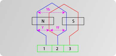
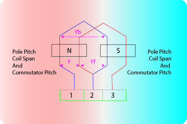
A coil connects with the commutator and is wound on the rotor. The number of the conductors or slots spanned by the coil is Front Pitch. “Yf” denotes front pitch.

Coil Span or Coil Pitch:
Coil Span or Coil Pitch is defined as the distance between the two sides of a single coil. It is in terms of the number of armature slots in between them (coil sides).
Lastly, after placing the coil into the slots how many slots are between the sides of the coil, this is the Coil span or Coil pitch. The Symbol for the coil span or coil pitch is “Ys”.
Pole Pitch:
Definition of the Pole Pitch-
Pole pitch is the peripheral distance between two adjacent poles of the machine (center to center). Armature peripheral under pole is (180-degree electrical). The symbol for the pole pitch is “Yp”. Pole pitch is measured in terms of the “Slots/pole” or “Conductors/pole”.
Formula-
Pole Pitch is equal to the total number of armature slots divided by the total number of poles of the machine. In short pole pitch formula is “slots per pole”.
How to calculate Pole Pitch-
For example, if there are 32 slots on the armature core and 4 poles. The number of the armature slots that come between poles will be 32/4=8. Hence, the pole pitch of the DC machine would be 8. Which is the number of slots per pole.
Slot pitch
Slot pitch is defined as the peripheral distance between the two adjacent slots. As it is a number so slot pitch is unitless. In DC machines, the Slot pitch approximately lies between 25 to 35 mm.
Commutator pitch
Commutator Pitch is defined as the distance between two commutator segments. Where two ends of the same Armature coil connect. So Commutator pitch is measured in terms of the commutator segments or bars. Since these are the numbers only, hence commutator pitch has no unit or is unitless.
Full pitched winding:
Definition of full-pitch winding –
A Full pitch winding is defined as the winding in which the two sides of the armature coil cover a distance equal to the pole pitch. The meaning of the Full pitch winding is Ys=Yp.
The Full pitch winding generates a maximum output voltage in the case of the Generator. Because EMF induces in one coil is with a 180-degree phase shift with EMF induced on another side of the same coil.
In this situation, two opposite sides of the coil lie under two opposite poles. one makes a magnetic North and the other produces a magnetic South pole.
Short pitched winding:
A Fractional pitch winding has a coil span less than a pole pitch (i.e, Ys<Yp). Therefore, this will be less than a 180-degree displacement between the coil sides.
The resultant EMF induced will be the vector sum of these two EMFs and of course less than the full pitched coils.
The main advantage of the short-pitched winding is that it is purposely used to affect copper saving. This saves copper used in the winding. It also improves commutation. DC machines are mostly Full pitch windings. [Generally short pitch windings are used to eliminate harmonics].
