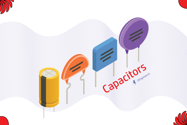
Generally, a capacitor is a Charge-storing element. It consumes the electrical energy and stores charge inside the Dielectric, up to the equilibrium attained with the applied voltage. As it stores electrical energy, it can be a source. When the source is absent, it connects to other passive elements. Which are the Resistor, Inductor, and Capacitor.
But, If the potential difference lasts inside the device. It provides energy as a source. As in the charging and discharging of a Battery. Also, I am discussing the capacitor definition, types, units, formulas, and symbols.
Table of Contents
What is a capacitor definition?
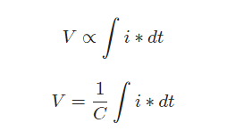
The terminal voltage is proportional to the integral of the current with respect to time. Alter, the current in a capacitor is equal to capacitance C times the rate of change of voltage. Hence, this is known as the definition of the capacitor.

Capacitor as Passive element
Since the active elements should be able to provide power or power gain to the circuit for an infinite duration of time. That is why the charged inductor and capacitor are not ACTIVE elements. Hence, these are PASSIVE elements.
Capacitor formula
The capacitance (C) of a capacitor is determined by the formula:
Capacitor formula: C=ε⋅A/d
where:
- C is the capacitance,
- ε is the permittivity of the dielectric material,
- A is the surface area of the plates,
- d is the separation between the plates.
What is Capacitance?
By definition, Capacitance is the ratio of Charge and voltage across the element. The unit of the capacitor capacitance is Farad, the symbol is “F”.
C=q/V
Types of the capacitors
- Parallel plate capacitors.
- Mica capacitors.
- Electrolytic capacitors.
- Paper capacitors.
- Film capacitors.
- Non-polarized capacitors.
- Ceramic capacitors
- power Film capacitors.
To illustrate we will discuss only a few capacitors of important types.
Parallel plate capacitor
The name itself explains that there are two parallel plates. Generally, parallel plates contain Dielectric material between them. These dielectric stores charge. When there is a potential difference between them. Hence, the charge storing capability depends on the dielectric inside.
C=ε⋅A/d
- C= charge in coulomb.
- A= Area of the plates.
- d= distance between the plates.
- epsilon(ε) for air is 1.
ε: depends on the dielectric placed inside!
Therefore, the Capacitance of the air as a dielectric is lesser. Than any other dielectric material inside. Because capacitance is directly proportional to the dielectric constant.
Mica capacitor
Mica capacitor is of two types. One uses natural minerals and the other uses silver mica as a dielectric.
“Clamped capacitor” uses natural minerals as a dielectric. Whereas “Silver mica capacitor” uses silver mica as a dielectric.
Clamped mica capacitors are obsolete due to their unwanted characteristics. The mica sheets are sandwiched together. Edges are coated with the metal to form silver mica capacitors. Then, this assembly dipped in the epoxy to protect the environment.
Mica capacitor meets the requirements for Stability, Reliability, and Small size.
Mica capacitors are low electrical loss capacitors. Used at higher frequencies this is stable chemically, mechanically, and electrically. Due to its crystalline structure binding, it has having typical layer-to-layer structure.
The most commonly used types of mica are phlogopite and muscovite mica. Muscovite mica has better electrical properties. Whereas phlogopite mica has better temperature resistance properties.
Electrolytic capacitor
Generally, if there is a requirement for large capacitance, the Electrolytic capacitor has that capability.
A thin metal layer is in use, for the one terminal, and on the other terminal, has a gelatinous substance (jelly or semi-liquid). The dielectric plate is a thin layer of oxide, it forms electro-chemically in production with the thickness of the film and it is less than ten microns.
Electrolytic capacitors have a thin insulating layer around them. It is also possible to make a capacitor of large capacitance. Which is having a very small distance between the terminals.
Capacitors must have a polarity check for the applied voltage. Otherwise, it will not work as needed, if it has some charge previously. If the polarity is not as needed, then its insulating oxide layer will break and the device will be damaged permanently.
The use of the Electrolytic capacitor is mainly in the DC power supply, to reduce harmonics in voltage waveform. Because these are having large Capacitance and small size. Also used for coupling and decoupling.
The disadvantage is their relatively low voltage rating. Because of the polarization of electrolytic capacitors
Paper capacitor
The paper or oil paper or thin wax paper separates two tin foil sheets. These paper sheets act as a dielectric. These sandwiched foils roll in cylindrical form. A plastic capsule encloses it. The two terminals of the capacitors connect to the two tin plates separately.
In the early ages, it used paper as a dielectric. As of now, the capacitors are using the materials like plastic sheets. That’s why it is called a “paper capacitor“.
The range of the paper capacitor varies from 0.001 to 2 microfarad. And the voltage rating is very high like 2000V.
Unit of Capacitance:
The unit of capacitance is the farad (F), named after the renowned physicist Michael Faraday. However, farads are often too large for practical use in electronic circuits, so capacitors are commonly measured in microfarads (μF) and picofarads (pF).
Capacitor Symbol
The symbol for a capacitor in circuit diagrams is two parallel lines representing the plates, with a gap indicating the dielectric material. The symbol is universally recognized in electronics and helps in identifying the role of capacitors within a circuit.
FAQ: Capacitor
What are the different types of capacitors?🤔
The different types of capacitors are as follows.
Electrolytic Capacitor
Mica Capacitor
Paper Capacitor
Film Capacitor
Non-Polarized Capacitor
Ceramic Capacitor
What are capacitors used for
Tiny electrical sponges, capacitors soak up and release energy, smoothing power, blocking unwanted currents, and storing bursts for cameras, flashes, and even your next song.
A number of capacitors, each of capacitance 1uF and each one of which gets punctured if a potential difference just exceeding 500 volt is applied are provided. Then an arrangement suitable for giving a capacitor of capacitance 3uF across which 2000 volt may be applied requires at least (A) 4 component capacitors (B) 12 component capacitors (CY48 component capacitors (D) 16 component capacitors
The answer is (C) 48 component capacitors.
Here’s how we get there:
1. 2000 volts is beyond the safe limit of each 1uF capacitor. Applying it directly would puncture them.
2. To handle 2000 volts, we need to reduce the potential difference across each capacitor. We can achieve this by connecting them in series.
3. In series, the capacitances add inversely: C_total = 1/ (1/C1 + 1/C2 + … + 1/Cn). For a desired C_total of 3uF with n 1uF capacitors, we need: 3 = 1 / (1/1 + 1/1 + … + 1/1 (n times)). Solving for n gives n = 48.
in which device the air capacitors are used
Air capacitors tune radio frequencies and spark flashes in cameras, both thanks to their precise, adjustable capacitance and ability to handle high voltages.
when are capacitors connected in series
Capacitors are used in series when:
1. They’re linked like beads on a string, positive to negative, sharing the same current.
2. Each capacitor stores the same charge, but the voltage divides across them.
3. The total capacitance is less than any individual capacitor, like adding resistances in series.
which type of capacitors are used in rf coupling circuit
Capacitors used in rf coupling circuit:
1. Multilayer Ceramic Capacitors (MLCCs)
2. Mica Capacitors:
3. Air Dielectric Capacitors:
why capacitor blocks dc
Capacitor blocks dc because the ability to store and release electrical energy in a cyclic manner prevents the continuous flow of DC, making it act as an open circuit for steady-state currents.
how to check capacitor with multimeter
To check a capacitor with a multimeter, set it to capacitance mode.
Connect the multimeter leads to the capacitor terminals, adhering to polarity. The multimeter will display the capacitance value, helping you assess the component’s health and determine if it falls within its specified range.
how to test a capacitor
To test a capacitor, use a multimeter in capacitance mode. Connect the multimeter leads to the capacitor terminals, observe the displayed capacitance value, and ensure it falls within the specified range.

Comments are closed.