What is Active, Reactive and Apparent Power

What is Real , Reactive and Apparent Power by ohmschool

In electrical engineering, understanding the types of power in an AC circuit is essential. The three key types of power are Active Power, Reactive Power, and Apparent Power. These terms help explain how energy is consumed, stored, and transferred in electrical systems. โšก What is Active Power? (True or Real Power) Definition:Active Power (also known … Read more

What is a Resistor? Definition, Unit, Symbol, Types, Color Code

what is a resistor definition unit symbol types color code

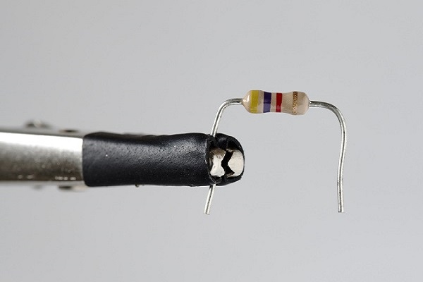
What is a Resistor? A Resistor is an electrical component that reflects electrical resistance to the circuit current. It is aย passive Elementย which means it only absorbs the electrical power. It cannot deliver power to the circuit connected with this element. Here we are discussing the Resistor definition, unit, symbol, types, color code, and applications. A … Read more

Inductor definition, symbol, unit, energy stored, formula, types & applications

Here I am talking about Inductor definition, symbol, unit, energy stored, formula, types, and applications. What is an Inductorโ€™s Definition? Definition of the inductor may be in many ways: By Definition, the inductor is an electrical/electronic circuit component that reflects some amount ofย resistanceย and inductance to the circuit. It is a helical path of the conductor … Read more

20 Applications, uses of Capacitors

Applications or uses of Capacitor

A capacitor is a passive electronic component that stores electrical energy in an electric field. It is made up of two conductive plates separated by a dielectric material. The conductive plates can be made of metal, aluminum foil, or other conductive materials. When a voltage is applied across the plates, an electric field is created … Read more

Difference Between Series and Parallel Circuits ๐Ÿ”Œ

Difference Between Series and Parallel Circuits

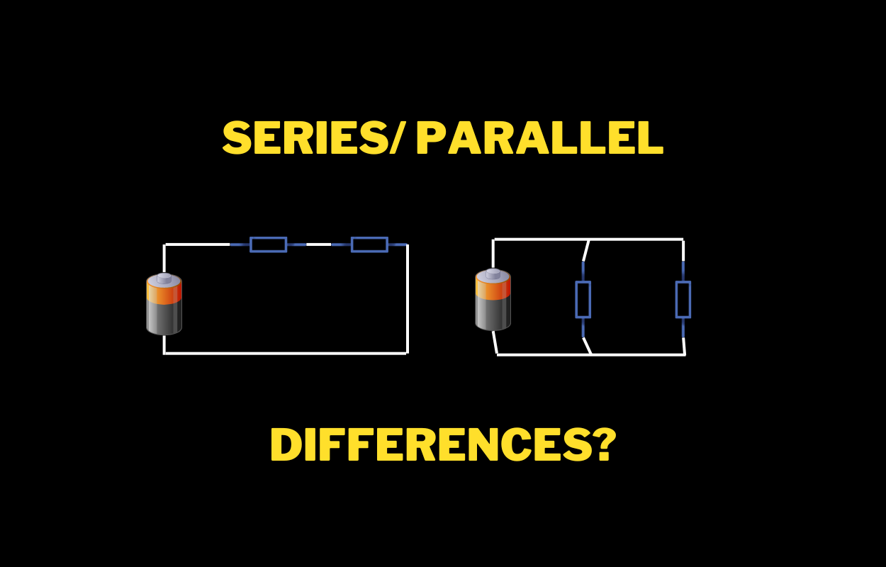
The main difference between a series circuit and a parallel circuit is the way the components are connected. In a series circuit, the components are connected end-to-end, so the current flows through one component and then through the next. In a parallel circuit, the components are connected side-by-side, so the current can flow through multiple … Read more

Difference between AC and DC

Difference between AC and DC OhmSchool

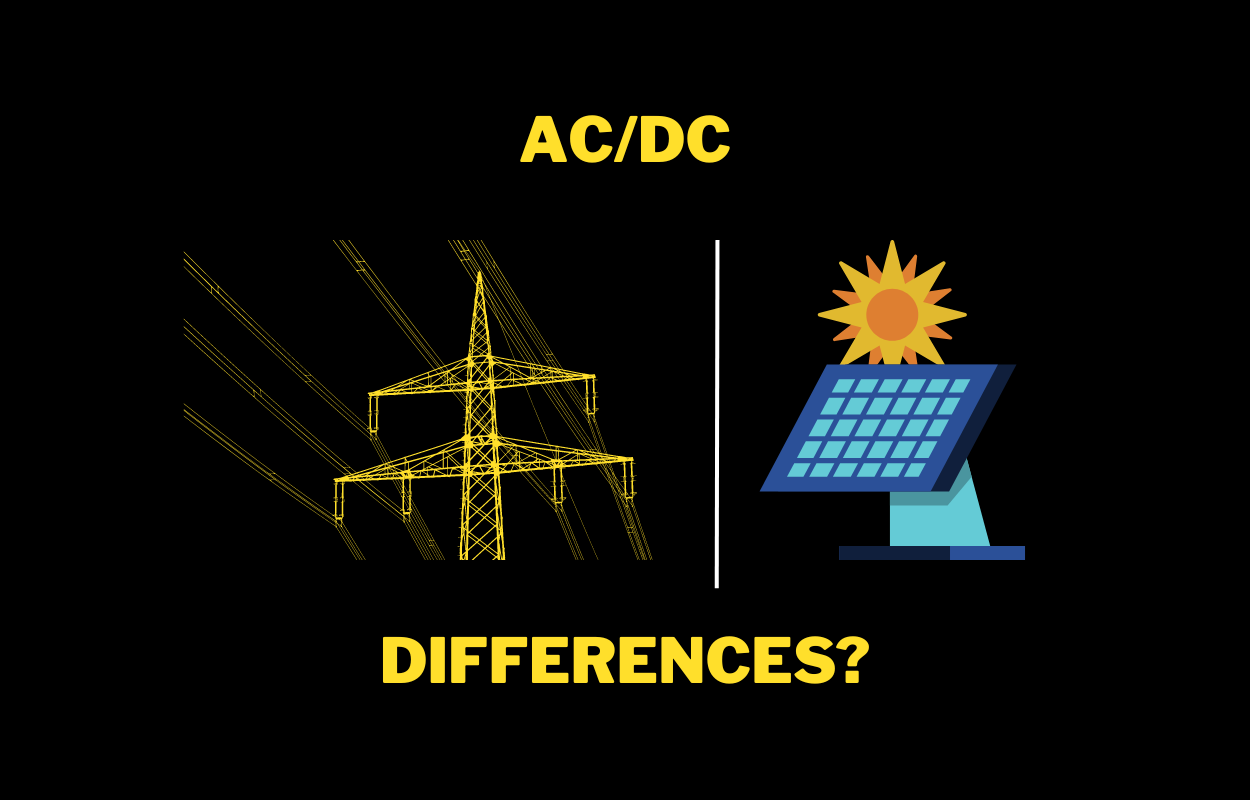
AC and DC are two types of electrical current, with the main difference being the direction of electron flow. In DC, electrons flow in one direction, while in AC, electrons switch directions periodically. AC is commonly used in homes and buildings and for long-distance power transmission, while DC is used in batteries and electronic devices. … Read more

Difference between Mesh and Nodal Analysis

Difference between Mesh and Nodal Analysis

The Main difference between Mesh and Nodal Analysis is that nodal analysis is an application of KCL (Kirchhoffโ€™s current law) whereas Mesh Analysis is an application of KVL (Kirchhoffโ€™s voltage law). This means Nodal analysis is used for calculating voltages at each node whereas Mesh analysis is used for calculating currents in the loop. Mesh … Read more

Difference between Capacitor and Inductor | Inductor vs Capacitor

Copy-of-Efficiency-of-transformer

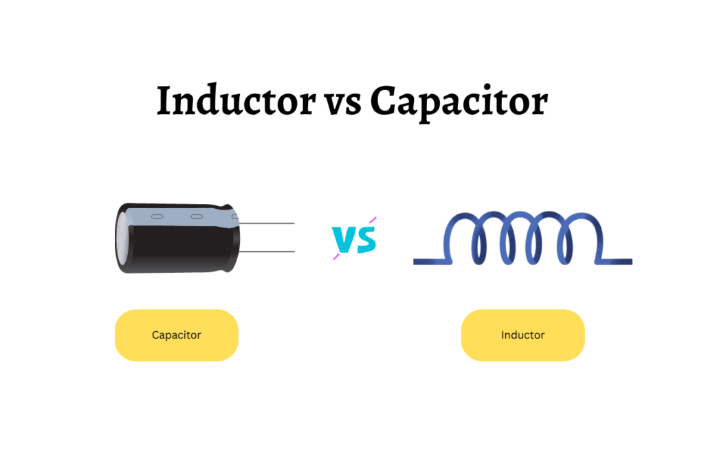
There are many differences between Capacitor and an Inductor but the main difference between a Capacitor and an inductor is that a Capacitor doesnโ€™t allow sudden variation of voltage across its terminals whereas an Inductor doesnโ€™t allow a sudden change in current through it. The capacitor stores energy in an electric field whereas the inductor … Read more

Voltage Divider: Rule, Formula, Examples

Generally, we need theย Voltage division Formulaย where there is aย Series networkย of the different elements like Resistor, Capacitor, or Inductor. We can use the Voltage Divider/Division Rule to find the voltage across each element of the circuit easily with examples. Then there is no need to apply KCL (Kirchhoffโ€™s current law) and KVL (Kirchhoffโ€™s voltage law) many … Read more

Nodal Analysis: A Comprehensive Guide

Nodal Analysis

What is Nodal Analysis? Nodal analysis is a method used in electrical engineering to determine the unknown voltages at nodes in a circuit. It is based on Kirchhoffโ€™s Voltage Law (KVL), which states that the sum of the voltages around a loop in a circuit must be equal to zero. How Does Nodal Analysis Work? … Read more