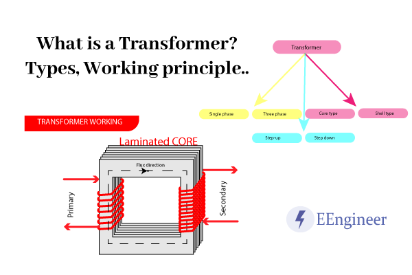
Continuous Electro-mechanical energy conversion takes place in an Electrical Machine. The transformer is not an Electrical Machine. It is a static device, that does not convert electrical energy to mechanical energy and vice versa. In Short, a Transformer is a thing in an electrical component that Steps up or down the voltage.
Table of Contents
The Step-up transformer increases the output voltage level whereas the Step-down transformer decreases the voltage level. But power input is equal to the output power. So it balances the current in the winding accordingly.
The transformer is a device that is a voltage-maintaining component. It meets the requirement where the load demands high voltage and supply is low voltage or vice versa.
What is a Transformer?
A Transformer is a Static Device in the Power Transmission system. Where the transmission current type is AC. It is most common for its voltage level changing capability from low to high or high to low. Instead of a change in the input and output powers.
A transformer is also a remedy for the low voltage level electronics component to use a high voltage source. High voltage steps down to meet the requirement of low voltage devices using a transformer.
Working principle of the Transformer
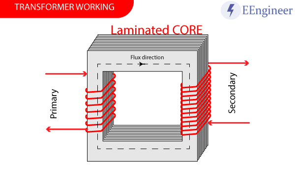
A Transformer works on the principle of Faraday’s law of electromagnetic induction as well as mutual induction.
A transformer consists of a Primary coil and a Secondary coil on the core. When an AC (alternating current) passes through its primary coil. It produces the magnetic flux around. Since the core has high permeability it allows all the flux to pass through it, leaking very little amount of flux. Now here the secondary winding (closed-circuited) is also present on the core. So by Faraday’s law of electromagnetic induction, a current is produced in secondary. The direction of the current produced is according to Lenz’s law.
Overall, a Transformer has the following working principle.
- Firstly, connect the AC source to the primary winding.
- Then flux is induced in the core.
- Afterward, due to Faraday’s law of electromagnetic induction, EMF is induced in the secondary winding.
- Lastly, if the secondary has a close circuit, a current is generated proportional to the transformation ratio. The direction of the current is by Lenz’s law.
Transformer Diagram
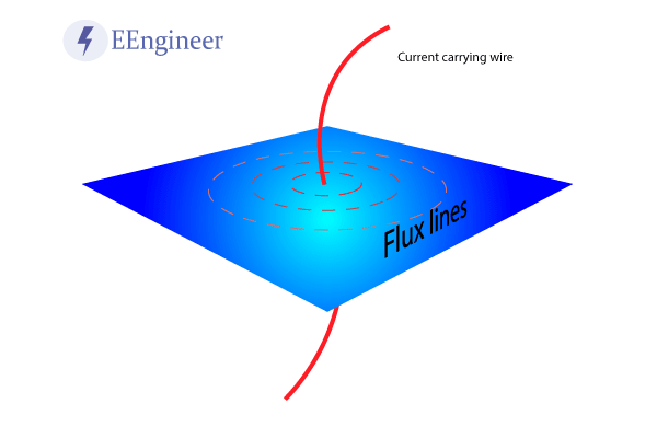
The above diagram shows a wire of the primary or secondary winding. When a wire is carrying alternating current it has a magnetic field around it. The direction of the magnetic field is by Flemming’s right-hand thumb rule. When this wire collectively as primary winding on the core. All the flux adds up and gives a strong magnetic field.
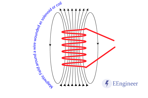
The above diagram shows a coil or wire-wound or solenoid. This is the application of the previous diagram. The direction of the flux is magnetic north to magnetic south inside the coil. Whereas outside the coil it is reverse as shown.
Note: As per the IEEE standard consideration primary and secondary side words are bad practices. They named them L.V and H.V sides. Where L.V stands for Low voltage side and H.V stands for High voltage side.
Transformer Types
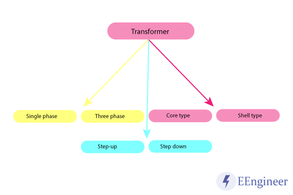
The transformer has various types based on the area of the application. These types divide into subcategories which are depending on the factors mentioned below:
- Medium of the core.
- Winding arrangement.
- Working voltage levels.
- Installation location.
Based on the Medium of the core
The transformer uses various types of the cores that are:
- Air core Transformer: Linking flux from primary winding to secondary winding travels through the air. Windings are wound on the non-magnetic strip.
- Iron core Transformer: Windings are wound on the parallel iron strips (sandwiched with the lamination) to prevent the eddy current loss.
Based on the winding arrangement
- Autotransformer: It has only one winding which is for both primary and secondary winding, using tappings. To know more about it click here.
Based on voltage levels
These are generally used for power distribution, transmission, and Generation to meet the requirement of the voltage levels.
- Step-up Transformer: These are having L.V. winding on the primary side and H.V. winding on the secondary side. They usually level up the voltage at the output.
- Step-down Transformer: These are having H.V side on the primary and L.V winding on the secondary side.
Based on the installation location
- Power Transformer: It is a static device that converts voltage levels from low to high or high to low without changing the frequency. It is also known as PT.
- Current Transformer: It is also denoted as CT. It reduces or multiplies an AC current without changing the frequency.
- Distribution Transformer: Mostly used in the distribution system for domestic purposes. They carry low voltage and easier to install and have low magnetic losses.
- Measurement Transformer: Mainly used in laboratories and in commercial applications to measure high voltage, current, and power.
- Protection transformer: They are used to protect costly electrical equipment. So the equipment which is needed to protect from large voltage fluctuations uses this.
Ideal Transformer
Here ideal means lossless. where:
- No loss. (core loss, iron loss, etc)
- Permeability is infinite.
