A logical AND Gate has two inputs and 3 inputs depending upon the application. It performs a logical multiplication rule to operate which means (A.B=Y). If either of the input is low (0) or (<5V), it gives the output signal also low. Whereas if all the inputs are in high state (1) or (=5V), the output of the sets to high (1). AND Gate may have any number of the inputs, where 2 and 3 inputs are the most common types.
Table of Contents
These gates are built in the Integrated circuits. These logic gates are made up of a specific arrangement of transistors. For modern microchips, the transistor is of Metal-Oxide-Semiconductor Field-Effect Transistor (MOSFET), and the semiconductor used is silicon.
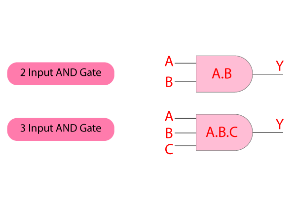
This gate logically multiplies the Binary digits zero (0) and one (1) to give the output ‘Y’. following is the logical AND Gate symbol:
In pneumatic system AND Gate is also called a DUAL PRESSURE VALVE.
The Truth Table
AND Gate truth table gives the idea that how the circuit is going to behave. In short, we can say, if either input is zero output will be zero. But only if all the inputs are one then only output is one. It is more elaborated in the truth table below.
2 input AND Gate
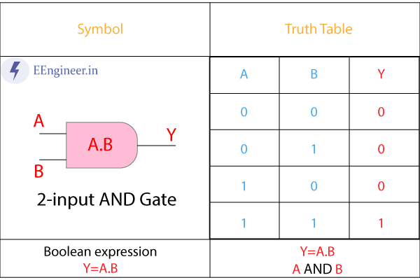
A 2-input AND gate have only two input terminals. AND output is the logical multiplication of those inputs.
This Gate is shown in the above diagram. where A and B are the inputs and Y is the output. A, B, and Y can be low or High logically. The logical operation of the 2-input and gate can be written as:
Y= A.B
Below is the 2- input AND Gate truth table. Where results for all the possible combinations are stated in the truth table.
3 input AND Gate
A 3-input AND Gate has three input terminals. Similar to the 2-input gate, the output is the logical multiplication of those inputs only. This logic is:
Y=A.B.C
Following are the 3 inputs AND Gate truth table. The symbol of the logical 3 input AND Gate is below:
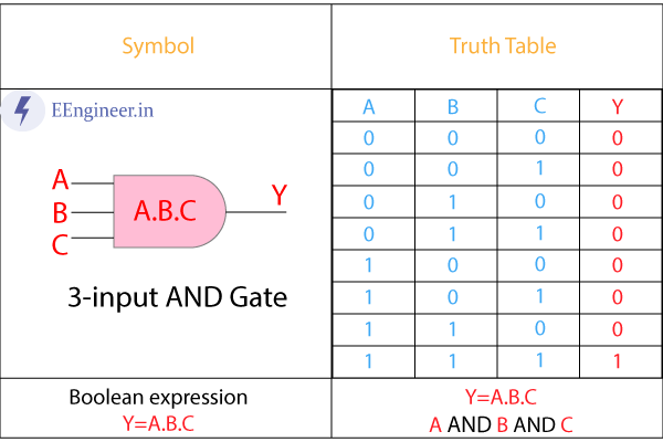
Hence, the output of AND Gate is 1 when all the inputs are 1. Whereas output of the AND Gate is 0 when any of the input is zero.
AND Gate using NAND
Basic logic gates (NOT, AND, OR) can be derived from universal logic gates (NAND, NOR). A universal logic gate is arranged such that it produces the output of the basic logic gates.
An AND Gate using a NAND gate is derived from involution property. Two NAND gates are used to make a single AND Gate.
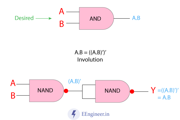
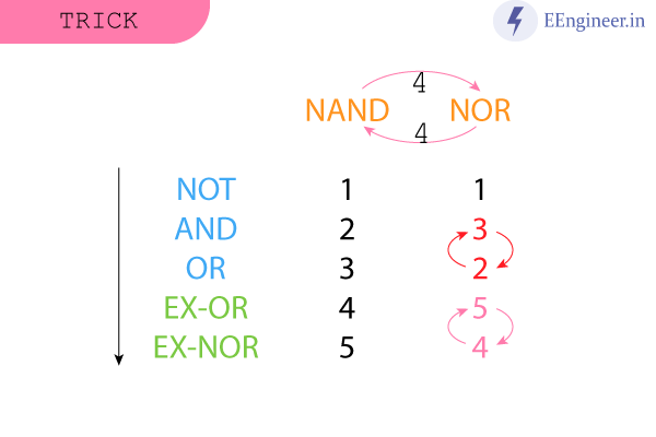
Further, you will see shortcuts to learn how many universal gates are needed to make a single basic logic gate.
Now the following table shows how many gates are needed to convert from NAND to AND gate.
